Satellite Technology
Digital satellite TV is significantly different to digital terrestrial TV - the most obvious difference being the satellite dish that is required to receive the signal, which requires quite precise alignment to the geostationary satellite to receive any signal. To get some idea of what satellite TV is all about, the following picture shows the Earth with geostationary satellites that can be viewed from the UK:
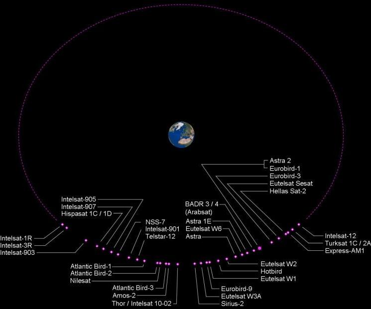
The picture is approximately to scale, with the Earth tilted so that the UK appears "in the middle" - hence the Clarke belt (where all geostationary satellites are located) looks slightly flattened. All of the satellites shown above are transmitting TV channels, though many of these are encrypted (such as Sky's premium service) and require some form of viewing card or access module to be able to receive the programme. Some of the satellites would also require a very large satellite dish to be able to receive a usable signal level, since the target audience is in the Middle East.
There are many more satellites (not shown above for clarity), arranged in a circle around the Earth, which serve different countries. Satellites over America can't be seen from the UK, since there is no direct line of sight (the Earth itself gets in the way).
Most of the programmes that UK viewers want are transmitted from Astra 2 at 28.2°E. This is actually a group of four satellites (Astra 2a, 2b, 2c and 2d), positioned close together, so that one dish can receive all of the signals. The Eurobird-1 satellite is located at 28.5°E, so its signals can also be received with the same satellite dish pointing at the Astra 2 satellites.
All geostationary satellites are at a nominal "height" of 35786m, directly above the equator, and match the Earth's rotation by travelling at a speed of 6877mph. Although each satellite is directly above the equator, dish antennas enable their transmissions to be directed at specific geographic regions. The transmission "footprint" for the Astra 2D satellite is shown below:
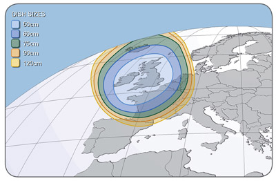
The small size of the Astra 2D footprint enables the satellite dish to be very small, and a 45cm "mini-dish" is frequently used for Sky. Other satellites with a larger footprint require a larger satellite dish. Effects such as rain fade with Sky reception can also be improved by installing a larger satellite dish.
All of the satellites are too far away to be observed by eye, but if they could be viewed directly they would form an arc in the sky with the highest point located at due South (the indicated satellite dish azimuths and elevations are for Torquay):

A typical satellite installation will have one dish directed at one satellite (or satellite cluster). To receive signals from more than one satellite, either a motorised dish can be used (which requires careful alignment to track the arc of the satellites across the sky) or a fixed dish can be used with an additional low noise block (LNB) and DiSEqC switching used to select the LNB / satellite required. The switching method can be used with satellites that are neither too close to each other nor too far apart. Several satellites can be received using this method, each one having its own LNB.
Satellite System
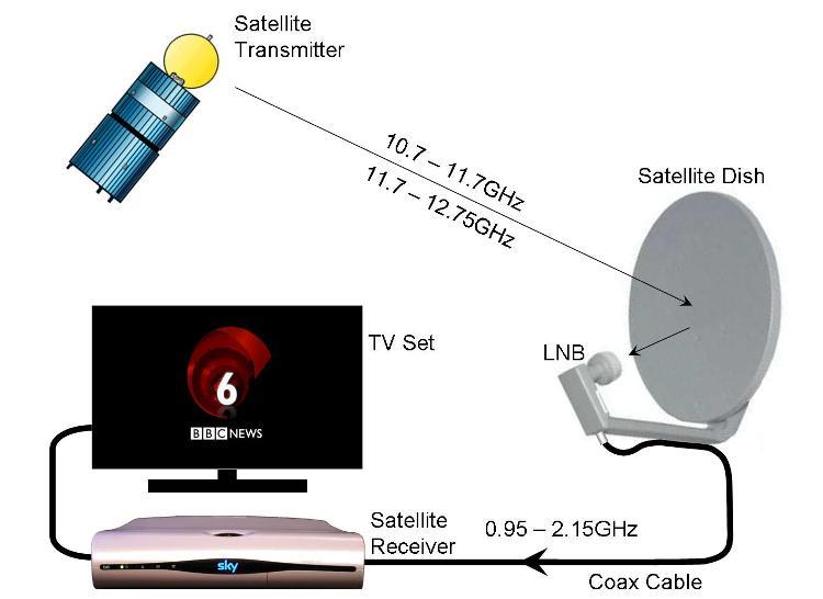
The signal from the satellite has a much higher frequency than terrestrial TV transmission (which uses 0.47 - 0.86GHz). Using a higher frequency gives a number of advantages, the main one being the increased programme capacity.
The satellite dish focuses the received signal onto the LNB, which amplifies the signal and converts it to a lower frequency (otherwise it would be completely lost by attenuation in the coax cable from the LNB to the satellite receiver). The satellite receiver provides power to the LNB via the coax cable connection, and selects the required programme from the received MUXs which is then viewed on the TV set (usually through a SCART cable).
Advantages of Satellite Transmission
Using just one satellite transmitter to cover the whole of the UK (instead of numerous transmitters required for terrestrial transmission) reduces interference problems and enables all of the transmission bandwidth to be used.
A direct line of sight from the satellite dish to the satellite transmitter is essential for satellite transmission - this is reckoned to be available for 98% of the UK population.
Using a high operating frequency allows more MUXs to be transmitted, which can carry more TV programmes and provides the additional capacity required for high definition programmes.
Each satellite MUX bandwidth (26MHz & 33MHz are used for Astra 2) is much wider than the Freeview bandwidth (7.6MHz), so each MUX can carry more programme content.
The Astra 2 satellites use both horizontal and vertical polarisation (transmitted separately) which doubles the available transmission capacity. The LNB on the satellite dish actually has two inputs - one for horizontal polarisation and one for vertical (described in more detail below).
A satellite dish antenna has a very high gain compared with a terrestrial TV aerial. This isn't immediately obvious, but it is a function of the physical size of the antenna and the operating wavelength (or frequency). A typical terrestrial aerial gain of 14dBi looks rather low when compared to a 60cm satellite dish with a gain of about 35dBi (an increase of 21dB = 126 times as much).
Disadvantages of Satellite Transmission
Whilst line of sight can be achieved for most people, 2% of the population have some form of obstruction between them and the satellite (could be a building, a hill or trees). The high frequencies used for satellite transmission give much less diffraction round obstacles, whereas lower frequencies used for terrestrial transmission will "bend" round obstacles to some extent.
Satellite reception requires a satellite dish, which has to be mounted outside. Any form of obstruction between the satellite dish and the satellite reduces the signal dramatically, so trying to use a satellite dish in a loft is a non-starter. A satellite dish will usually work through glass however, so it could be housed in a greenhouse or conservatory in principle.
Satellite reception typically has a very low margin, and depends quite heavily on error correction to maintain picture quality. A consequence of this (and the high operating frequency) is that atmospheric effects like rain reduce the signal strength, and in heavy rain reception can be lost completely.
Satellite transmissions include many subscription services, which may include a minimum contract period (e.g. 12 months for Sky), though many Sky channels are unencrypted and can be received without a viewing card on a non-Sky satellite receiver. At the moment, Channel 4 and Five are encrypted and require a Sky receiver (which need not be on a Sky contract) and a Freesat viewing card (which requires a one-off payment of £20 to Sky). In due course, Channel 4 and Five will become unencrypted and hence will be available as part of the Freesat service.
The high gain of the satellite dish makes it quite sensitive to alignment - the beamwidth is only a few degrees, so accurate alignment is required and needs to be maintained. Since the dish is relatively large, it has a high wind loading, so is best located in a sheltered spot and needs to be securely attached using substantial brackets.
Although the LNB converts the ~11GHz signal down to ~1.5GHz so the signal can be carried down a coax cable to the satellite receiver, the cable loss is higher than for terrestrial TV, and the frequency dependence of this loss needs to be taken into account for long cable runs. Typically, installers will aim to minimise the cable length between the LNB and the satellite receiver.
Recording a satellite TV programme whilst watching a different programme requires two satellite receivers (just the same as Freeview terrestrial TV). LNBs are available that provide multiple outputs (each one requiring its own coax cable), so only one satellite dish is required, but after that things become slightly complicated. Twin tuner satellite receivers are available (though are expensive), but:
| A Sky+ box (twin tuner & PVR) needs a Sky subscription to record |
| A non-Sky receiver cannot use the Sky EPG |
The new Freesat service launched on the 6th May 2008 carrier its own specific EPG and hence is fully independent from the Sky EPG.
Satellite Dish Installation
Planning restrictions may apply to satellite dishes in conservation areas, National Parks and areas of outstanding natural beauty. Restrictions may also apply to listed buidings and buildings with thatched roofs. For a large dish (over 1m in diameter), or a second dish (larger than 60cm) planning consent will be required. For most people, planning consent will not be required; however it is the responsibility of the home owner (not the installer) to check if permission is required.
A satellite dish should be installed where it is inconspicuous, otherwise the local authority may insist on it being removed and repositioned at the owner's expense. See the Householder's Planning Guide for more information.
Satellite dishes may be painted to match their background without compromising the performance of the dish, provided non-metallic matt paint is used (reflective paint could give sufficient heat from the sun to damage the front of the LNB!).
Standard satellite dishes are made from either steel or aluminium (more expensive), but can also be made from transparent plastic (with a "see through" metallic coating) to reduce the visible impact.
For any dish installation, a clear view to the satellite is essential, which will not become obstructed by growing plants and trees, or by a neighbour's house extension.
LNB Operation
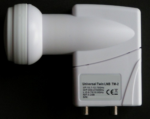
The LNB collects the high frequency radiation (which is focused by the surface of the satellite dish) and converts this into lower frequency electrical signals (so the coax cable can cope!). The input end of the LNB has a short section of circular waveguide, incorporating a flared transition.
At the bottom of the waveguide are two probes that convert the received signal (as a waveguide mode) into a coax / microstrip mode (similar to the dipole on a terrestrial TV aerial feeding a coax cable). The two probes are perpendicular to each other and each one samples one polarisation only, giving two independent signal outputs.
The relative probe positions are difficult to see in the photo above - a sketch of the sideways cross-section looks like this:
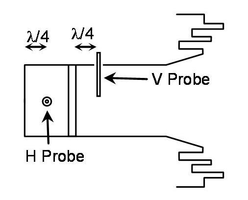
The H probe (for picking up the horizontally polarised signals) is nearest the bottom end of the waveguide. The flat metal end of the waveguide is a short circuit (for any polarisation), and the probe is positioned ¼ wavelength away to pick up a maximum induced voltage on the H probe. The V probe is positioned further "up" the waveguide, together with a dowel pin across the vertical diameter of the waveguide, positioned ¼ wavelength away. The dowel pin presents a short circuit only to the vertically polarised signal, and has no effect on the horizontal polarisation.
The LNB "down converts" the received signal from the satellite by mixing it with a local oscillator (L.O.). The difference in frequency is then amplified and passed down the coax cable to the satellite receiver. Two L.O.s are used in the LNB; one for the "low" frequency range (10.7 - 11.7GHz) and one for the "high" frequency range (11.7 - 12.75GHz). The LO frequencies are as follows:
| L.O. Frequency | Input Frequency | Output Frequency |
|---|---|---|
| Low = 9.75GHz | 10.7 - 11.7GHz | 0.95 - 1.95GHz |
| High = 10.6GHz | 11.7 - 12.75GHz | 1.1 - 2.15GHz |
This requires the LNB to be able to select from four input signal options:
| Input Polarisation | Low Freq. MUXs L.O. = 9.75GHz | High Freq. MUXs L.O. = 10.6GHz |
|---|---|---|
| Horizontal | 10.7 - 11.7GHz (H) | 11.7 - 12.75GHz (H) |
| Vertical | 10.7 - 11.7GHz (V) | 11.7 - 12.75GHz (V) |
This is achieved via the coax cable to the LNB by using two voltage levels (13V = vertical, 18V = horizontal) and a 22kHz tone (no tone = low L.O. frequency, 22kHz tone = high L.O. frequency):
| Input Polarisation | Low Freq. MUXs L.O. = 9.75GHz | High Freq. MUXs L.O. = 10.6GHz |
|---|---|---|
| Horizontal | 18V d.c, 22kHz OFF | 18V d.c, 22kHz ON |
| Vertical | 13V d.c, 22kHz OFF | 13V d.c, 22kHz ON |
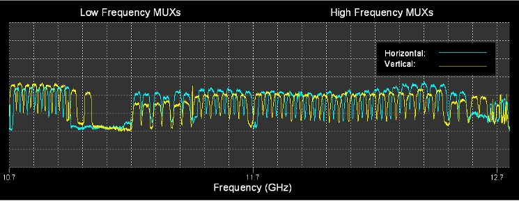
This effectively gives a fourfold increase in capacity, and explains how one satellite location can transmit so many different programmes. The following chart shows the full set of MUXs transmitted from the Astra / Eurobird satellite group at 28.2°E / 28.5°E:
The 22kHz tone can also used for switching between two LNBs (using a DiSEqC switch) or to drive a motor to position a moveable dish (using a suitable interface box). This is achieved by pulsing the 22kHz signal.
LNBs are usually specified with a noise figure, with a lower number being supposedly "better" (i.e. less noise). These days, LNBs are typically specified with noise figures of 0.2dB or 0.3dB, where previously they would have been specified as 0.6 - 0.8dB. This is not because LNB performance has improved dramatically, but because a low noise figure is regarded as "better". Unfortunately, noise figures much below around 0.8dB are impossible to measure using any "honest" measurement system, and correspondingly the performance of a 0.2dB LNB may well be identical to an older 0.8dB LNB. The upshot is that the noise figure specification has become rather meaningless.
Satellite TV Installation and Distribution
A standard satellite installation uses a single coax cable from the LNB to the receiver. Since the LNB is effectively forming a part of the tuning circuit (by its ability to select between horizontal or vertical polarisation and between a low L.O. and a high L.O.), a dual LNB is required for Sky+ (or similar twin tuner PVR receiver) together with two coax cables from the LNB to the receiver. Where two coax cables cannot be installed, stacker / de-stacker units can be used.
Independent satellite receivers (e.g. in different rooms) can be fed from a single satellite dish and LNB, provided the LNB has sufficient outputs (e.g. two independent Sky+ receivers will require a quad LNB, with two coax cables to each receiver (or stacker / destacker units where only one cable is available).
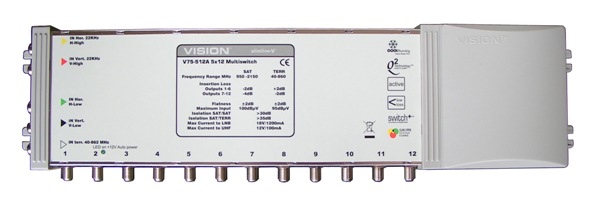
For distribution to every room in a house, one satellite dish can be used with a quattro LNB to supply each room with its own satellite service. The quattro LNB provides each of the four output options (low L.O. horizontal, low L.O. vertical, high L.O. horizontal and high L.O. vertical) on separate / individual output connectors. Each of the four outputs from the quattro LNB is fed into a multiswitch, which provides the necessary matrix switching, splitters and amplifiers to enable any input to be routed to any of the multiple outputs. The routing operation of the multiswitch is still determined by the DC voltage and 22kHz tone from each satellite receiver.
This is the same principle used to distribute a satellite TV service around a block of flats, with all rooms being fed from a single satellite dish. Where a Sky+ or similar twin tuner satellite receiver system is being installed, twin coax cables are required to each room, which effectively halves the available outputs on a multiswitch unit.
N.B. Each subscription satellite receiver will still require its own viewing card.
For hotels, the prospect of a satellite TV distribution system may be of interest. There are two ways of implementing satellite TV in a hotel:
| a) One satellite receiver in each room. |
| b) A remote bank of satellite receivers (one for each channel), with a UHF distribuiton system. |
Hotel owners may not be especially enthusiastic at the expense of one satellite receiver in every room, but this does offer the widest range of TV programmes to the guest.
Using a remote array of satellite receivers restricts the available TV programme selection to the number of satellite receivers used - one satellite receiver provides one TV programme. The RF output of these satellite receivers can then be fed to a UHF distribution system, hence allowing existing analogue TVs to continue to be used.
For a Sky TV distribution system in a hotel, a business subscription will be required, which includes limitations on the TV channels and the number of channels that can be distributed.
For domestic systems the UHF output on the rear of a Sky box can be used to feed the received TV programme to a second remote TV set (e.g. in the bedroom). By using a remote eye device, the Sky box can be operated from the remote location as if it were actually in the same room, allowing channels to be changed, the Sky box to be switched off etc. The Sky system uses a 7MHz modulation to carry the infrared signals, as well needing the 9V enabling (to power the remote eye) on the RF2 socket at the rear of the Sky box, hence isolated wall plates will prevent the remote eye system from working.
The 7MHz system only operates with Sky boxes - similar devices are available for non-Sky satellite receivers, but these use an additional IR emitter close to the satellite receiver to implement the remote control commands.

